
The Cruellest Cut Pt.1: Splitting Models in Meshmixer
- The Italianmoose

- Apr 22, 2020
- 4 min read
Updated: Apr 26, 2020
Getting some models to print can be a bit of a pain. With injection moulded parts you often see them broken down into smaller bits. Manufacturers do this to ensure it is physically possible, with the manufacturing process involved, to create the parts reliably. You have a lot more flexibility with 3D printing but in some cases it can still be very beneficial to cut a model up:
- You want to avoid having too much support material. Particularly support material placed on a top surface of the model and reaching to the underside of another part.
- You want to hide the underside of the print in joints in the model
- It's too big for your print bed
Alternatively you may want to assemble a model from parts:
- To make small components part of a larger model. This often results in more reliable prints.
- To have less gluing to do. Why get a load of small parts when you don't need them?
I'm going to cover both cutting and joining in this and future posts.
Generally I design my models with FFF manufacturing in mind. Resin printing is more flexible and the supports are less unsightly so you don't have to consider design for manufacture as much. While even with the best set-up FFF printer supports can ruin fine surface details.
There's a lot of ways of doing cutting. I'm going to cover two ways here, in Meshmixer and by importing STEP files into a CAD program. Meshmixer works with the STL files you can download, while STEP files are a bit more uncommon in modelling. STEP files are the PDF of geometry. All CAD software packages can open them, as can some 3D modelling programs.
First, I'm going to go through Meshmixer. This is another piece of Autodesk software (I swear I'm not a fanboy!), and is available free from http://www.meshmixer.com/download.html
Load up the software, and flick through the slides below so you can see what I'm on about.


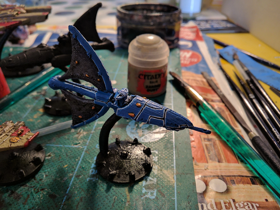
I'm going to use a few different models for demonstrations. First-off I'm going to use an Eldar Wraith, available from: https://cults3d.com/en/3d-model/game/eldar-cruiser-3.
So, with your model downloaded hit "Import" in Meshmixer and navigate to the file. Down the left-hand side you've got all your major controls. There's a number of useful tools of manipulating the model. The key ones for us here are "Transform", which is for scaling and moving objects; and "Plane Cut", which is for cutting models apart.
Now we have to consider. Right-click and drag rotates the camera, mousewheel zooms, and middle mouse button and drag moves the camera. Moving the camera about, to get a good cut for print, I would slice it one of two ways:
- Right down the middle to give two mirrored sides
- Around the waist to give prow and rear hull sections
To do either of these, we need to open up the "Plane Cut" tool. This now gets quite involved. For "Cut Type", the two key options are "Cut (Discard Half)", "Slice (Keep Both)", or "Slice Groups". Cutting it in two is poorly behaved unless you choose "Cut (Discard Half)". I would leave "Fill Type" as "Remeshed Fill".
In the image you can see a complex triad of the main controls, and a ring with other controls. In that triad, the arrows translate the plane. The triangles next to the arrows allow for freer translation in that plane. The arc segments are for rotation.
Around the ring there are four buttons which have no tooltips. The top right buttons affect how the plane transforms are referenced: locally "L" to the model or to the world "W". The bottom left buttons are for snapping the plane transform. "S" turns on snap, and "A" when activated allows for transforms in absolute space, referenced to the origin of Meshmixer. So if the plane is 40 mm above the origin, the transform control move reads as 40 mm. If this is disabled the plane transform value will start at zero at the start of each transform. However it's a bit stupid as the snapping doesn't affect rotation. To snap rotation move your cursor to the cross marks around the ring. My advice is have a play with them to get a feel for how they behave. The last blue arrow is for flipping the slice normal, which only matters if you're throwing away half the model. I'm cutting this model down the middle, for when I want the most surface material on the print bed. Joining the two halves after printing is quite easy, especially with a slow setting glue so you can get it aligned.


So with a couple of plane rotations I've got it cutting right down the model. Hit accept to perform the cut! Next hit export, and give the file a different name. Congratulations! You've cut a model in half and hopefully made your life easier. The final image is the model imported into Cura, the software I use for slicing, then mirroring one half and arranging it for print. This means you get a whole Wraith in one go! That brim is used to keep the model flat on the bed, as the plastic cools it has an annoying habit of lifting off and ruining the print. This print just has that brim, which is an absolute doddle to remove, then with a bit of filing you can get a seamless join between the two halves. I do this with a lot of my Eldar ships, particularly those with two coplanar sails like the Wraith as the end result is much neater than printing the sails vertically. The downside is the big prow lances can lose some detail as they're split in two.
Next time, I'm going to go through more advanced cutting in Fusion 360.


Comments