
You CAD! Fusion 360 tips: Lofty ambitions
- The Italianmoose

- May 18, 2020
- 4 min read
One of the many reasons I prefer CAD software over stuff like Tinkercad or Sketchup is that you can make much more complex geometry in minutes. An excellent example are Imperial prows. To look good they need a very smooth curve. Here are some of my models in drydock:

These were printed at ~0.06 mm layer height (adaptive) on my printer, Junkpile-1. The key to making those prows are the lofts you can create in CAD packages. You can visualise a loft as creating a tubular shape that you're constraining and then filling with material. In Fusion 360 the tool sits in the Design space under Create -> Loft. In Solidworks my only advice is sacrifice a goat and hope it leads you to the right button (I don't have a copy handy to check where the button lives, and Solidworks' UI drives me nuts).
To create basic lofts you want two shapes to mark the start and end of the body. I'm going to do a very boring example with rectangles:


So what we've done here is create two sketch profiles, one on an offset plane, and then created a loft between them, which effectively joins the profiles to form a body. You can see in the loft tool there are a number of options. You can join several profiles together to make more complex shapes, and use guide rails to control how the shapes are formed:


The first image adds a third circular profile. You can see how it goes smoothly from a circular shape to a rectangle. In the second image I've gone nuts and added a spline between the centres of each sketch to constrain the loft along a path to create a really funky shape. Guide rails are the key to getting the shape you want. You can also think of basic extrustions as trivial lofts. Lofts can be used to both create and remove material.
Let's now look at our Imperial prow:

In your head, divide it up into shapes that have been created from lofts, extrusions, and Fusion 360's press/pulls. I design my ships in halves and then mirror the halves. This saves an awful amount of work. Let's drill down into this prow a bit more.


In the first image you can see all the sketches that go into the basic shape. There's quite a few! I usually try to avoid 3D sketches but in this one they're essential for creating a good guide for the ribs on the sides of the prow. 3D sketches are a nightmare to manage, they're not sat on a nice well-behaved plane anymore. These have been locked between the fully defined sketches above and below them to keep them in place.
In the second image you can see the loft tool setup itself. Getting Fusion 360 to correctly select the right profiles for the top and bottom takes a bit of fiddling and careful selection. Generally clicking on the profile in the tool and then using Ctrl-click to select/deselect will get the job done. Prepare for a lot of internal screaming at this stage. I've used guide rails that constrain the outsides of the shape, which MUST connect the extremities of the profiles. The loft will follow them between the profiles. Rails 1, 5, and 6 constrain the basic shape of the prow, while rails 2, 3, and 4 hold the ribs in place. Careful readers will notice I've missed selecting a rail! Thankfully it makes almost no difference.
The third image shows the shape of the basic sketches. Other than lines, my most used sketch shape is a conic curve. This allows these sweeping turns with easier control than splines. All the curves in this image are conics! The little dots are the "foci" of the conics (not mathematical foci, those would be inside the concave side). You can adjust the position and weight of the foci to control how much the curves bend and their shape.


Next, we add another little loft for the rib midway up the prow, and another to form the top of the prow. We then punch circular holes in the back to refine the shape, and add yet another loft to join the ribs neatly. Then the little triangular bit is formed with an extrusion which sticks out past the edge of the hull, which is then cut with a loft between two profiles matching the hull outer surface in the third image.


Next we form the prow eagle with some extrusions, chamfers, and a revolve. A few extra extrusions on the base to give some interest there. I left room for a nova cannon or prow ram. The torpedo tubes could use a closer look:
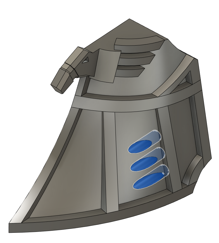
These are formed with an extruded cut of three circular profiles into the prow from the front. If the tubes go too deep it's worth extruding the bottom out a bit individually for neatness. Using an extrude like this makes sure the torpedoes can exit the tube without hitting any other part of the prow! Finally we mirror and combine the half-prow to create the whole, and there we go! One lovely imperial prow.
At a later date I'll cover lofts in Tau and Eldar ships, and where it's sometimes best to avoid the pain a loft can cause if you can get the effect some other way. Fillets will feature greatly!
Did you enjoy this? I always appreciate pizza: https://www.buymeacoffee.com/italianmoose


Comments